Basic Power Supply Application Guide
There are four basic types of power supplies used:
- Unregulated Linear
- Regulated Linear
- Ferroresonant
- Switch Mode
The differences between the four types include constant voltage output, cost efficiency, size, weight, and ripple. This guide explains each type of supply, describes the principle of operation, and outlines the advantages and disadvantages of each.
1. Unregulated Linear Power Supply
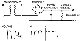 Unregulated power supplies contain four basic components: a transformer, rectifier, filter capacitor, and a bleeder resistor.
This type of power supply, because of its simplicity, is the least costly and most reliable for low power requirements. The disadvantage is that the output voltage is not constant. It will vary with the input voltage and the load current, and the ripple is not suitable for electronic applications. The ripple can be reduced by changing the filter capacitor to an IC (inductor-capacitor) filter but the cost to make this change would make use of the regulated linear power supply a more economical choice.
2. Regulated Linear Power Supply
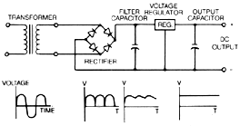 A regulated linear power supply is identical to the unregulated linear power supply except that a 3-terminal regulator is used in place of the bleeder resistor.
The regulated linear power supply solves all of the problems of the unregulated supply, but is not as efficient because the 3-terminal regulator will dissipate the excess power in the form of heat which must be accommodated in the design of the supply. The output voltage has negligible ripple, very small load regulation, and high reliability, thus making it an ideal choice for use in low power electronic applications.
3. Ferroresonant Power Supplies
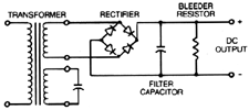 A ferroresonant power supply is very similar to an unregulated power supply except for the characteristics of the ferroresonant transformer.
The ferroresonant transformer will supply a constant output voltage over a wide variation of the transformer input voltage. The problems with using a ferroresonant power supply include that it is very sensitive to slight changes in line frequency and would not be switchable from 50 Hz to 60 Hz, and that the transformers dissipate more heat than conventional transformers. These power supplies are heavier and will have more audible noise from the transformer resonance than regulated linear power supplies.
4. Switch Mode Power Supplies
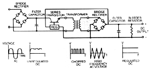 The switch mode power supply has a rectifier, filter capacitor, series transistor, regulator, transformer, but is more complicated than the other power supplies that we have discussed. The schematic below is a simple block diagram and does not represent all of the components in the power supply.
The AC voltage is rectified to an unregulated DC voltage, with the series transistor and the regulator. This DC is chopped to a constant high frequency voltage which enables the size of of the transformer to be dramatically reduced, and allows for a much smaller power supply. The disadvantages of this type of supply are that all of the transformers have to be custom-made and the complexity of the power supply does not lend itself to low production or economical low power applications.
Rectification Circuits for Regulated Linear Power Supplies
From our previous description, a regulated linear power supply is the most economical design for lower power, low ripple, and low regulation which is suitable for electronic applications. In this section we will explain the four basic rectification circuits that are used:
- Half Wave
- Full Wave Center Tapped
- Full Wave Bridge
- Dual Complementary
1. Half Wave Circuits

Since a capacitor input filter only draws current from the rectification circuit in short pulses, the frequency of the pulses is half that of a full-wave circuit, therefore the peak current of those pulses is so high that this circuit would not be recommended for DC power more than 1/2 watt.
2. Full Wave Center Tapped Circuits

A full-wave rectifier uses only one-half of the transformer winding at a time. The transformer secondary rated current should be 1.2 times the DC current of the power supply. The transformer secondary voltage should be approximately .8 times the DC voltage of the unregulated power supply per side of the center tap or the transformer should be 1.6 times VDC center tapped.
3. Full Wave Bridge

The full-wave bridge rectification circuit is the most cost effective because it requires a lower VA rated transformer than a full-wave rectifier. In a full-wave bridge, the entire transformer secondary is used on each half cycle, unlike the full-wave center tapped which only uses one-half the secondary on each half cycle. The transformer secondary rated current should be 1.8 times the DC current of the power supply. The transformer secondary voltage should be approximately .8 times the DC voltage of the unregulated power supply.
4. Dual Complementary Rectifier
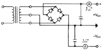
A dual complementary rectifier is used to supply a positive and negative DC output of the same voltage. In most cases, the negative current is significantly less than the positive current requirements so the AC voltage and current relationship to the DC voltage and current should be the same as the full-wave center tapped described earlier.
How to Specify the Transformer
The use of a regulated linear power supply is to provide a constant output voltage over a variety of loads and also a variation of the input voltage. All of our calculations to determine the correct transformer will assume that the input voltage can vary from 95 to 130V and not change the output of our supply.
The formula used to determine the AC voltage required from the transformer is as follows:

- Vdc= Output voltage
- Vreg=Voltage drop of the regulator =3v
- Vrec=Voltage drop across diodes=1.25V
- Vrip=Ripple voltage=10% of Vdc
- Vnom=115V
- Vlowline=95V
- .9=Rectifier efficiency
We have summarized all of the calculations for three basic rectification circuits in the table below:
| Rectification Circuit | RMS VOLTAGE (VOLTS) | RMS CURRENT (AMPS) |
|---|---|---|
| Full-Wave Center Tap | Vac C.T. = 2.092 x Vdc + 8.08 | IAC=IDC x 1.2 |
| Full-Wave Bridge | Vac=1.046 x VDC +4.04 | IAC=IDC x 1.8 |
| Dual Complementary | VAC CT= 2.092 X VDC =8.08 | IAC=IDC x 1.8 |
There are low loss regulators which have .5V drop instead of 3V but they are not being considered at this time because of availability.
EXAMPLES:
Example #1:
A regulated linear power supply is needed for 5VDC at 1 ADC with a primary of either 115V or 230V and you do not know whether it should be full-wave center tapped or a full-wave bridge.
| Full-Wave Center Tap | |
|---|---|
| Vac C.T.=2.092 x Vdc + 8.08 | Iac = Idc x 1.2 |
| Vac C.T.= 2.092 x 5 + 8.08 | Iac + 1 x 1.2 |
| Vac C.T. = 18.54 C.T. | Iac = 1.2 |
| VA = 18.54 x 1.2 = 22.5 |
| Possible choices for the transformers are: | |
|---|---|
| 4-02-6020 | UL PC mount |
| 4-05-4020 | Low profile |
| 4-07-6020 | UL Chassis mount |
| 4-42-3020 | VDE PC mount |
| 4-44-6020 | VDE PC mount |
| 4-47-3020 | VDE Chassis mount |
| 4-49-4020 | VDE Chassis mount |
| Full-Wave Bridge | |
|---|---|
| Vac= 1.046 x Vdc + 5.23 | Iac = Idc x 1.8 |
| Vac = 1.046 x Vdc + 5.23 | Iac = 1 x 1.8 |
| Vac=10.46 | Iac = 1.8 |
| VA = 10.46x 1.8 = 18.83 |
| Possible choices for the transformer are: | |
|---|---|
| 4-02-6010 | UL PC mount |
| 4-05-4010 | Low profile |
| 4-07-6010 | UL Chassis mount |
| 4-42-3010 | VDE PC mount |
| 4-47-6010 | VDE PC mount |
| 4-47-3010 | VDE Chassis mount |
| 4-49-4010 | VDE Chassis mount |
Example #2:
A regulated linear power supply is needed for 12 VDC at 250MA DC with a single primary voltage 115 V and a full-wave bridge is the rectification circuits that you will use.
| Full-Wave Bridge | |
|---|---|
| Vac= 1.046 x Vdc + 4.04 | Iac=Idc x 1.8 |
| Vac= 1.046 x 12 + 4.04 | Iac = .25 x 1.8 |
| Vac= 16.59 | Iac = .45 |
| VA = 16.59 x .45 = 7.47 |
| Possible choices for the transformer are: | |
|---|---|
| 4-01-5020 | UL PC mount |
| 4-03-4020 | UL PC mount |
| 4-05-3020 | UL Low Profile PC mount |
| 4-06-5020 | UL Chassis mount |
| 4-41-2020 | VDE PC mount |
| 4-44-5020 | VDE PC mount |
| 4-46-2020 | VDE Chassis mount |
With power supplies, be sure that the regulator chosen adequately heat sinked to dissipate the power at high line full load.
Example #3:
A regulated linear power supply is needed for ± 15VDC at 50MA with a 115 volt primary.
| Dual Complementary: | |
|---|---|
| Vac CT=2.092 x Vdc x 8.08 | Iac = Idc x 1.8 |
| Vac CT = 2.092 x 15 + 8.08 | Iac= .050 x 1.8 |
| Vac CT = 39.46 | Iac= .090 |
| VA =39.46 x .090 = 3.55 |
| Possible choices for the transformer are: | |
|---|---|
| 4-01-4036 | UL PC mount |
| 4-03-3040 | UL PC mount |
| 4-05-2040 | UL Low Profile PC mount |
| 4-06-4036 | UL Chassis mount |
| 4-44-4036 | VDE PC mount |
Let us now look at how the regulator will dissipate heat in worse case conditions high line(=130V) and full load. The regulator dissipates the excess power in the form of heat. A regulator has only a maximum amount of power it can dissipate before the internal thermal protection shuts it down. If a 5VDC, 1AMP power supply can operate at 95V RMS, the regulator will have to dissipate 5.95 watts at full load high line (see calculation below).
Regular dissipated heat:


